CULPEOWASH
A Product by Hydraulic Foxtrot
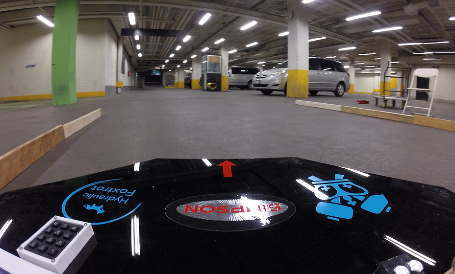
CulpeoWASH utilizes various sensors to navigate around its environment and ensure an even wash. The combination of ultrasonic sensors and a digital compass ensure that it operates in an optimal fashion. The placement of distance centers around the chassis of the robot ensures that no collisions occur during the robot’s operation and that it does not fall off of the deck that it is washing. The digital compass is used for the robot to maintain a straight-line motion while implementing PID control to stay on track, even on rough terrain. The robot’s body will be made of acrylic that is sealed with a waterproof caulk so water does not leak into the electronics system. Various electronic components are also placed in waterproof seals so that no damage occurs to the system during operation. Laser cutting and 3D printing are the main methods of manufacturing, providing an affordable overall cost. The video above is beta-testing of CulpeoWASH with pressurized water, while video below is the beta-testing of CulpeoWASH with unpressurized water. As demonstrated in the video above, the robot will be placed such that the cables and cords will always follow the device to avoid any tangling.
VIDEOS
CulpeoWASH Operation with Pressurized Water
CulpeoWASH Beta-Testing
CulpeoWASH Prototype Video
HIGHLIGHTS
PID CONTROL SYSTEMS
CUSTOMIZED CLEANING PREFERENCES
ZIG-ZAG MOTION
USER-FOCUSED DESIGN

ENGINEERING ANALYSIS
Force, Torque, and Trigger Control Analyses
This section will provide an overview of the engineering analysis.
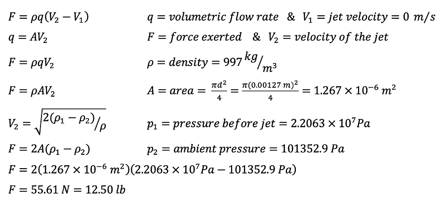
FORCE ANALYSIS ON THE ROTATING NOZZLE
Our primary concern is if the robot will be lifted by the pressure, but the weight of the robot is enough to keep it grounded
Evenly cleans because the nozzle rotates at 1500 rpm
No matter the orientation, the circular cleaning area is not affected

TRIGGER CONTROL FORCE ANALYSIS
The goal of this analysis is to make sure the water is immediately turned off if the robot were to topple over.
In this instance the accelerometer must be able to communicate to a mechanical water control system to cut off the water source from the attached pressure washer.
This is done by a linear actuator that pushes against the trigger and activates the water actuating button of the trigger gun.
By measuring the angle of the trigger lever arm with respect to the horizontal needed to press on the gun button and using the equation on the right, we found the torque needed to activate the gun to be 1.876 ft−lbs.
Our desired linear actuator is the 10 mm Stroke L12-I Micro Linear Actuator, which is capable of activating the trigger gun.

TORQUE ANALYSIS ON THE MOTORS
The motors will be required to move both the device and the trailing tether.
The device will weigh approximately 34 lbs and the tether will be dependent on the length of the hose and power cord in use.
Using a standard power cord, the average added weight from the power cord is 7 lbs. The hose will add an additional 5 lbs of weight that the motors will have to move.
This brings the total weight up to 46 lbs. For this reason we oversized the motor to include a factor of safety.
The torque on the motors can apply 106.28 oz−in before it is geared down.
The torque experienced by the motors in relation to the entire assembly is calculated using the equation on the right, which is below 106.28 oz-in.